Leaks cause fines and claims. Clay alone struggles. You need a barrier that resists puncture and stays stable on slopes with simple procurement and fewer site passes.
Composite geomembrane is a geomembrane bonded to one or more geotextiles. It combines a low-permeability barrier with cushion and friction. You get stronger puncture resistance, safer slopes, and faster installation with one delivered roll.
You may buy for a landfill, a canal, or a process pond. This guide explains what is composite geomembrane, shows advantages and types, maps uses, and gives clear selection, manufacturing, and installation checks from a factory view for real projects.
What is composite geomembrane?
Specs differ by sector. Confusion wastes time. Clear terms protect your budget and your schedule.
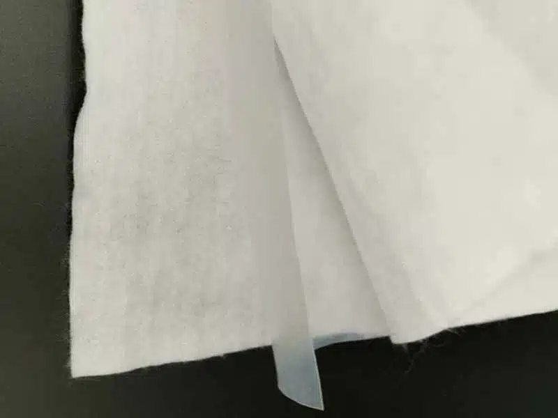
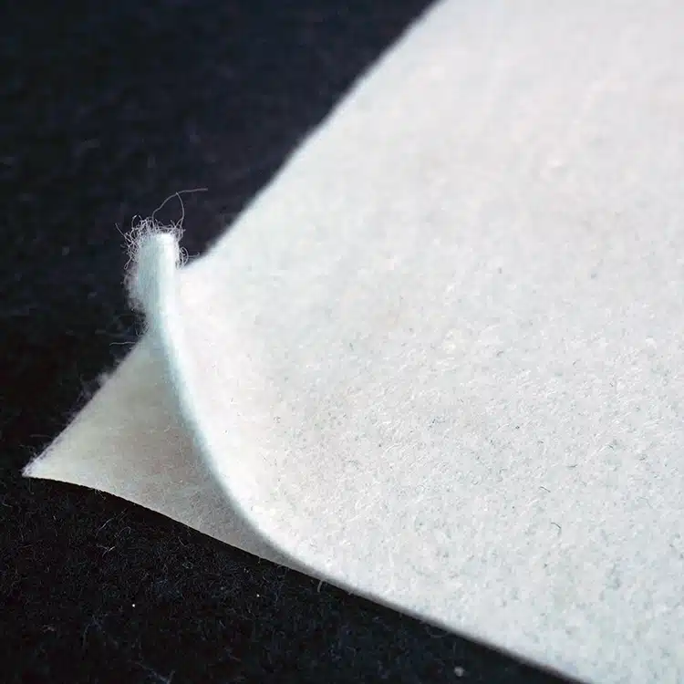
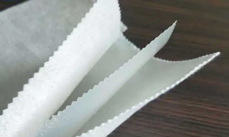
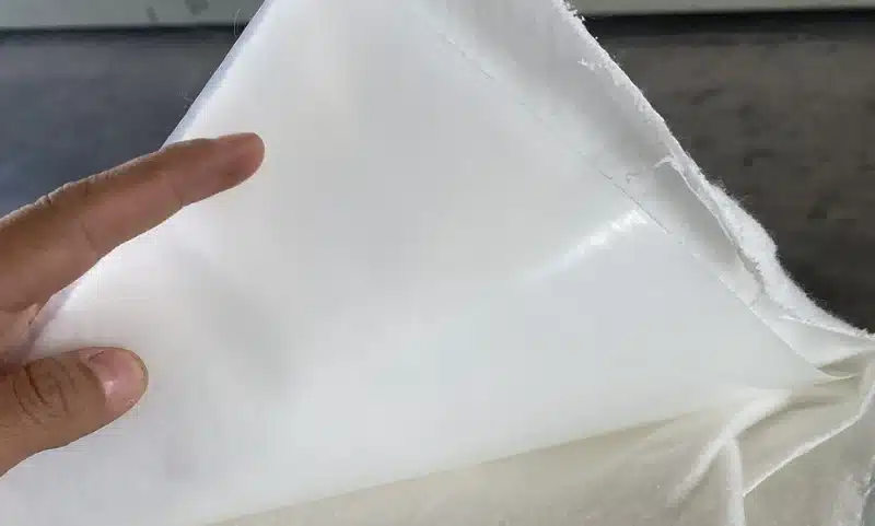
Composite geomembrane is a laminate that bonds a polymer geomembrane to a geotextile on one or both sides. The membrane blocks liquids and gases. The geotextile adds cushion and friction. Installers weld the membrane core; the geotextile protects and stabilizes the system.
Dive deeper
A composite has a geomembrane core—most often HDPE or LLDPE—and nonwoven geotextile (PET or PP) that is bonded by thermal or extrusion lamination. You can specify one-side composite (GM + GT) or two-side composite (GT + GM + GT). The geomembrane provides the barrier function with very low permeability. The geotextile spreads point loads, raises puncture resistance, and increases interface shear against soils, GCLs, and other geosynthetics. This mix reduces damage during cover placement and improves slope stability during construction and service. You should name the membrane resin, thickness, geotextile mass per unit area, lamination peel strength, tensile/elongation, carbon black and OIT for durability, and interface shear for the exact pairs in your design. In the field, welders make membrane-to-membrane seams; details keep geotextile fibers clear of the seam zone. Composite geomembrane works as part of a system: prepared subgrade, underlayment where needed, composite liner, drainage and venting layers, and cover soil or concrete. Keeping hydraulic head low above the barrier and maintaining clean seams are more important to leakage control than adding unnecessary thickness. Good specs, clean roll IDs, and a simple CQA plan reduce risk and speed acceptance.
What are the advantages of composite geomembrane?
Thin membranes tear under angular cover. Smooth liners can slide on steep slopes. Multiple separate layers slow crews and raise damage risk.
Composite geomembrane increases puncture resistance, improves slope friction, and speeds installation by combining barrier and cushion in one roll. You reduce defects, simplify logistics, and meet specs with fewer SKUs and fewer field passes.
Composite liners deliver performance and productivity. First, the bonded geotextile disperses point loads from gravel and rocky cover. The membrane sees lower peak stresses, so you log fewer punctures and fewer patches. Second, geotextile nap raises interface shear. Slopes that would be marginal with smooth GM move into safer factors of safety. Third, crews handle one product instead of laying separate cushion geotextile and a bare membrane. Fewer alignments and fewer roll changes reduce exposure to wind, dust, and damage. Fourth, seam zones stay cleaner because the geotextile shields the membrane from scuffs and foot traffic, and installers can trim GT back to expose a fresh, weldable membrane strip. On the commercial side, a composite reduces inventory complexity and receiving errors: one label, one certificate pack, one traceable roll ID. In audits, a composite shows clear logic: the barrier plus its protection are inseparable, so responsibility for cushion is not split between trades. The key checks for buyers are simple: confirm geotextile mass is high enough for your cover soil, confirm lamination peel strength meets spec so layers do not separate during handling, confirm interface shear with the exact soil or geosynthetic pairs, and keep OIT/UV targets appropriate for exposure and temperature. These steps lower total cost more than chasing the lowest price per square meter.
Types of composite geomembrane?
One cap detail is not like another. You need the right layer count, resin, and geotextile mass for your slope, cover, and chemistry.
Composite geomembranes come in standard layer configurations with defined geotextile weights and membrane thickness ranges. Choose the configuration that matches your slope, cover soil angularity, and handling needs.
Dive deeper
Below are the common Composite Geomembrane Specifications used in real projects. I keep the ranges broad so you can align with national specs and project classes.
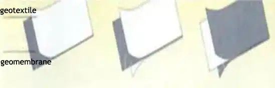
1) One geotextile + one geomembrane (1+1).
Geotextile: 100–1000 g/m².
Geomembrane thickness: 0.1–1.5 mm.
Use when one interface needs cushion or friction, for example canals (GT down) or pond slopes (GT up). This type reduces layers and protects against subgrade or cover soil on the chosen side.
2) Two geotextiles + one geomembrane (1+2).
Geotextiles: 80–600 g/m² each side.
Geomembrane thickness: 0.2–1.5 mm.
Use on caps and steep slopes where both interfaces need protection and higher friction. This is common on landfill caps and reservoir side slopes.
3) One geotextile + two geomembranes (2+1 sandwich).
Geotextile: 100–1000 g/m².
Each geomembrane thickness: 0.1–0.8 mm.
Use when you need a barrier redundancy or specialty performance (for example, conductive detection layer or different textures) while keeping a protective cushion on one side.
4) Many geotextiles + many geomembranes (multi-layer).
Geotextiles: 100–1000 g/m².
Each geomembrane thickness: 0.1–0.8 mm.
Use for special builds that require staged protection, extra friction, or inspection layers. This configuration serves complex slopes, tunnel systems, or heavy cover with angular rock.
Core resins. HDPE for harsh chemistry and long life; LLDPE for higher flexibility and easier detailing on irregular subgrades. Surface options. Smooth or textured core. Textured cores increase friction and may allow lighter geotextiles on some slopes.
| Config | Typical fit | Strengths | Watch-outs |
|---|---|---|---|
| 1+1 | Canals, ponds | Simple, fast, targeted cushion | Choose side and AOS carefully |
| 1+2 | Caps, steep slopes | Highest friction both sides | Slightly heavier rolls |
| 2+1 | Redundant barriers | Inspection options, special duties | More seams and detailing |
| Multi | Tunnels, heavy covers | Custom friction and protection | Design and QC complexity |
Define side orientation in the layout plan. Keep seam zones free of fibers. Tie each layer to a test method and a certificate.
What are composite geomembrane used for?
You may need a cap over waste, a canal lining, or a process pond slope. The composite gives protection and friction in one step.
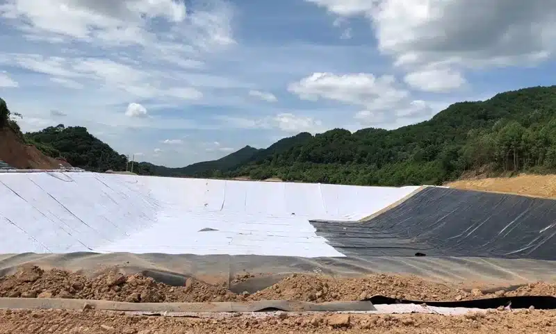
Composite geomembrane is used for landfill caps, pond and canal linings, reservoir slopes, secondary containment, tunnel waterproofing, tailings cover systems, and aquaculture ponds where cushion and cleanability both matter.
Dive deeper
Sector map with quick guidance
- Landfill caps: Two-side composites under protective soil limit puncture from cover placement and raise slope stability. Add gas vents and drainage above.
- Ponds and reservoirs: One-side composites protect against subgrade gravel or against cover soil, depending on side. LLDPE cores fit long runs and movement.
- Canals: One-side composite with the geotextile down cushions against subgrade. Textured core helps on side slopes.
- Mining and tailings covers: Composites on capping layers resist puncture from rocky cover and support steeper faces.
- Secondary containment: Around tanks and loading pads, composites protect the barrier from ballast and improve friction under traffic plates.
- Tunnels and underground works: As part of a waterproofing build-up, composites add cushion behind shotcrete or precast.
| Sector | Typical stack | Key risk | Control |
|---|---|---|---|
| Landfill cap | GT/GM/GT composite + drainage + soil | Slope slide | Double-textured core or heavier GT |
| Reservoir | GM/GT or GT/GM | Thermal movement | Anchor trench and expansion detail |
| Canal | Composite + toe keys | Subgrade points | Underlayment check and repair |
| Mining cover | Composite + rocky cover | Puncture | High GT mass, test pad |
| Secondary containment | Composite + ballast | Joint stress | Factory boots and fillets |
Match the composite to the interface that needs the most help: the rougher or steeper side gets the geotextile and, if needed, texture.
How is composite geomembrane manufactured?
Poor bonding fails in transport or during cover placement. Good bonding survives welding, loading, and time. Buyers should know the basics.
Composite geomembrane is produced by laminating a polyethylene membrane to geotextile using controlled heat and pressure or hot-melt extrusion. Plants test thickness, mass, peel strength, tensile, OIT, carbon black, dispersion, and roll identity for traceability.
Dive deeper
Plants use extrusion lamination or thermal calendering to bond layers. Extrusion lamination lays a thin melt film that fuses GM to GT, giving strong and uniform peel strength when temperature, nip pressure, and speed are controlled. Calendering uses heated rollers and pressure; it is effective for uniform surfaces and stable geotextiles. For textured cores, the process preserves texture height for friction while keeping seam zones weldable. Factory CQC covers membrane thickness profile, geotextile mass per unit area, peel and shear strength of the bond, membrane tensile/elongation, OIT (standard and high-pressure) for thermal life, carbon black content and dispersion for UV durability, and full roll labels with ID, lot, date, and dimensions. Buyers should ask for a sample CQC report before large orders and verify that seam margins are kept clear of GT fibers so field welds are clean. During installation, crews weld membrane-to-membrane with dual-track wedge seams and air-channel tests. The lamination must not peel near seams when the GT is trimmed back. A short trial weld each shift confirms wedge parameters, and field peel tests confirm seam strength. This manufacturing and QC flow gives you traceability from resin to seam, which protects you in audits and claims.
How do I install and test composite geomembrane?
Supply is half. Field work decides outcomes. You control risk by writing clear steps and tests into the tender and purchase order.
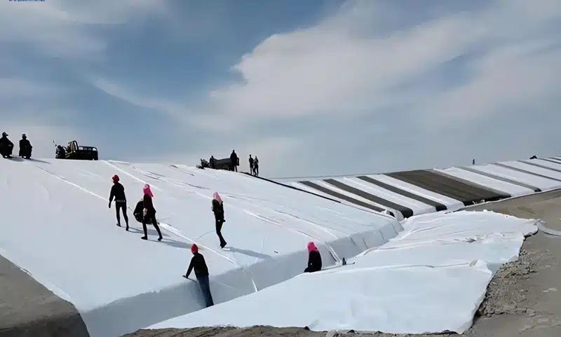
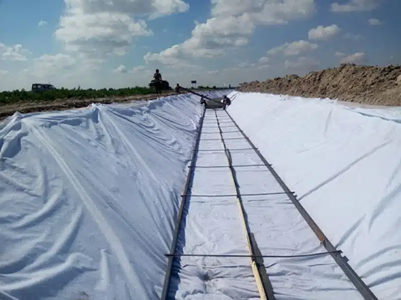
Install on smooth, compacted subgrade. Place panels with wind and fall. Weld membrane-to-membrane with calibrated wedge. Test every seam. Protect the composite before cover placement. Keep full records for acceptance.
Dive deeper
Prepare the pad to final grade, proof-roll, and remove protrusions. Use underlayment geotextile where subgrade is rough. Lay out panels in the main drainage direction and orient the GT side toward the interface that needs cushion or friction. Trim GT back at seam zones if the detail requires a clean membrane strip. Make dual-track wedge seams to form an air channel for non-destructive testing. Log temperature, speed, and pressure. Use extrusion beads for T-joints, boots, and patches after a light grind. Anchor at crests with trenches or clamps; backfill and compact. Place cover from the toe upward with low-drop methods; do not traffic bare composite. Testing must include air-channel pressure on wedge seams, vacuum box on extrusion seams, destructive shear/peel coupons at set frequency, and lamination peel checks on representative samples to confirm bond after handling. For steep slopes or material changes, verify interface shear before production. Documentation should include panel and seam maps, roll IDs, trial seam records, weather logs, and photos. Accept only with a complete as-built pack. Risks to watch: delamination from low bond or rough handling (control with peel spec and handling rules), slope slides from low friction pairs (control with textured core and higher GT mass), puncture from angular cover (control with heavier GT and underlayment), seam leaks from dust or moisture (control with cleaning and NDT), and wrinkles from heat and time (control by installing in cool hours and pinning early).
My opinion
Composite geomembrane works best when buyers treat it as a system. Order the composite with underlayment, drainage geonet, boots, vents, and a written test plan in one package. Standardize on a few configurations—1+1, 1+2, and one textured-core option—and pre-approve CQC before mobilization. These small steps save more money than chasing the lowest sheet price.
FAQ
Which configuration should I choose?
If one side is rough, use 1+1. If both sides are rough or steep, use 1+2. For redundancy or inspection layers, consider 2+1 or multi-layer.
What ranges are available?
Typical ranges: 1+1 GT 100–1000 g/m², GM 0.1–1.5 mm; 1+2 GT 80–600 g/m² each side, GM 0.2–1.5 mm; 2+1 GT 100–1000 g/m², each GM 0.1–0.8 mm; multi-layer GT 100–1000 g/m², each GM 0.1–0.8 mm.
HDPE or LLDPE core?
Choose HDPE for harsh chemistry and long life. Choose LLDPE for flexibility and easier detailing.
Can crews weld through geotextile?
No. They weld membrane-to-membrane. Trim GT back to expose clean seam strips.
Do I still need drainage?
Yes. Drainage above the barrier reduces head and lowers leak rates if defects exist.
How do I verify quality?
Ask for resin and GT certificates, lamination peel tests, OIT and carbon black data, dispersion class, and keep roll IDs tied to seam maps.
Is composite geomembrane good for canals?
Yes. Use 1+1 with GT down to cushion subgrade. Consider textured core on side slopes.
Does composite replace a GCL?
No. It can sit over a GCL in composite liners. Each layer has a role.
What about exposed service?
Raise UV and OIT targets and set inspection intervals. Consider colored or specialty surfaces if regulations allow.
Conclusion
Match configuration to interfaces, set bond and interface shear tests, and weld clean membrane seams. With the right composite and a simple QA plan, you cut damage, raise stability, and close projects faster.