How to Stabilize a Slope with Geogrid?
Landslides, veneer slips, and blown budgets—sound familiar? Pick the right geogrid and install it right, and U lock slopes down for decades.
For steep slopes use uniaxial geogrid; for veneer control use biaxial. Nail site assessment, drainage, layer spacing, anchor trenches, and 95% Proctor compaction. Follow the step-by-step sequence below to deliver reliable reinforced soil slopes.**

Below is a compact, standards-anchored playbook U can hand to crews: selection (uniaxial vs. biaxial), design inputs, materials and tools, installation steps, QA checks, common failure traps, and post-install maintenance—plus an MJY factory checklist for procurement.
Which geogrid should U use for this slope?
Wrong grid, wrong direction, wrong result. Match reinforcement to the dominant stress path.
Uniaxial geogrid provides high tensile capacity in one direction for steep slope stabilization; biaxial geogrid balances strength both ways for veneer stability and embankment bases. Choose by slope angle, load, and drainage risk.**

Uniaxial vs. biaxial—fit for purpose
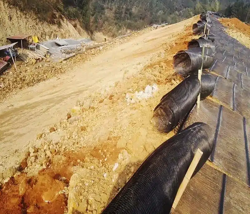
- Uniaxial (UX): Highest modulus/tensile in machine direction (MD). Go-to for steep slopes (>45°), tall reinforced soil slopes (RSS), and mechanically stabilized earth (MSE) where reinforcement must resist outward thrust primarily in one direction.
- Biaxial (BX): Balanced MD/CD stiffness. Best for veneer stability, surficial erosion control, and foundation/base stabilization where loads act multi-directionally.
Quick selection matrix
| Design Factor | Use Uniaxial When… | Use Biaxial When… |
|---|---|---|
| Slope angle | > 45° (steep/tall RSS) | ≤ 45° or for veneer/cover stability |
| Dominant load direction | Lateral thrust is primary | Loads/traffic act both directions |
| Objective | Structural reinforcement | Surface restraint + base stabilization |
| Facing | Wrapped face / geogrid wrap / MSE blocks | Vegetated veneer / erosion control mats |
How should U assess the site before design?
Guesswork is expensive. Measure what controls stability.
Confirm geometry, soils, groundwater, and surcharge. Plan drainage first, then define layer spacing, embedment, and face detail. Document assumptions before mobilization.**

Core inputs to collect
- Geometry: Slope height (H), angle (β), benching plan, and available setback.
- Soils: Unit weight, friction angle/cohesion, gradation, plasticity; note weak interlayers.
- Hydro: Groundwater level, seep zones, springs, seasonal runoff.
- Loads: Surcharge (pavement, traffic, structures), seismic if applicable.
- Drainage: Feasible toe drains, chimney drains, swales, outlets.
Design levers U control
| Parameter | Typical Guidance (project-dependent) | Why it matters |
|---|---|---|
| Vertical spacing (Sv) | 6–18 in (150–450 mm) | Closure of potential slip surfaces |
| Embedment length (Le) | 0.7–1.0 × H (RSS) or per calc | Anchorage beyond active wedge |
| Overlap (side-by-side) | 6–12 in (150–300 mm) | Load transfer between rolls |
| Facing detail | Wrapped face or erosion control mat | Controls veneer slip/erosion |
| Compaction target | ≥ 95% Standard Proctor (ASTM D698) | Mobilizes interlock and stiffness |
What materials and tools do U need on site?
Crews cannot execute a spec with the wrong kit. Stage what drives quality.
Bring the correct geogrid type/strength, clean granular backfill, anchor hardware, drainage pipe with filter fabric, and compaction gear. Pre-cut rolls and lay down a clear QA checklist.**

Core materials
- Geogrid: Uniaxial for steep/RSS; biaxial for veneer/base. Verify long-term design strength (LTDS), junction efficiency, and aperture match to backfill.
- Backfill: Well-graded, free-draining (avoid high fines). Target moisture for compaction.
- Toe drain: Perforated pipe + graded gravel wrapped in geotextile.
- Anchoring: U-pins/staples; sandbags for temporary ballast.
- Erosion control: Turf reinforcement mat (TRM) or ECB for face.
Tools & QA checklist
| Item | Purpose |
|---|---|
| Vibratory plate / small roller | Achieve ≥95% Standard Proctor |
| Utility knives/shears | Trim grid without frayed edges |
| Tension bars/frames | Pull grid taut pre-pinning |
| Measuring/marking gear | Layout benches, Sv, overlaps |
| Safety gear (PPE) | Gloves, eye protection, high-traction boots |
How do U install geogrid on a slope step by step?
Sequence builds strength. Change the order, and U weaken the system.
Prepare subgrade, excavate the anchor trench, orient and tension the grid, place 6–8 in lifts, compact to 95% Proctor, repeat to design height, and finish the face with wrap or mat.
Field sequence (crew card)
- Prepare subgrade: Clear vegetation/rocks; proof-roll to find soft spots; grade smooth.
- Cut anchor trench (crest): Typical 12 in × 12 in (300 × 300 mm), 3–5 ft behind crest; confirm with design.
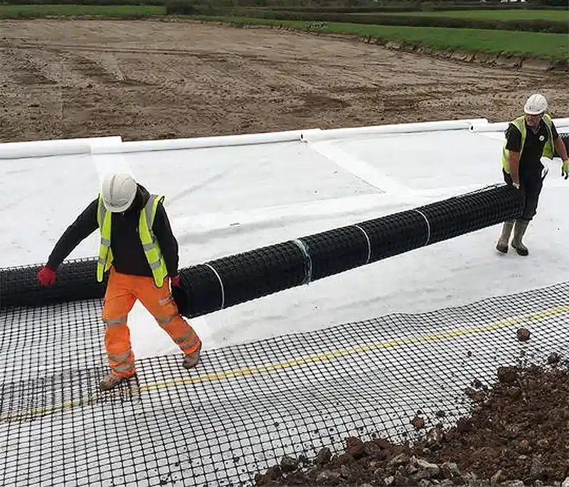
- Roll & orient: For UX, run strong direction up/down the slope (perpendicular to face). For BX, align square to the face.
- Tension & secure: Pull taut; pin at crest and along edges. Maintain 6–12 in overlaps between adjacent rolls.
- Place backfill: Spread 6–8 in (150–200 mm) lifts; keep ≥ 6 in loose fill between equipment and grid.
- Compact: Target ≥95% Standard Proctor each lift; avoid pushing the face out of alignment.
- Repeat layers: Maintain specified Sv; check embedment length Le into stable zone.
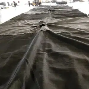
- Finish face: Wrapped face (fold geogrid back) or vegetated veneer with TRM/ECB.
Key hold points (inspect before proceeding)
| Hold Point | Acceptance Intent |
|---|---|
| Subgrade smoothness | No protrusions → no puncture starters |
| Orientation & overlaps | Strength direction correct; laps consistent |
| Compaction per lift | Density achieved; no bridging/voids |
| Drainage placed/functional | Toe drain connected and free-flowing |
What mistakes kill slope jobs—and how do U avoid them?
Most failures aren’t material defects—they’re preventable process errors.
Avoid wrong orientation, thin or wet lifts, skipped drainage, and inadequate overlaps. Keep equipment off bare grid and secure edges immediately to stop wind uplift.**
Common pitfalls & fixes
| Pitfall | Consequence | Fix |
|---|---|---|
| UX laid parallel to face | Zero reinforcement engagement | Always run MD perpendicular to slope face |
| Skipped toe drain | Hydrostatic blow-out at face | Install/perf pipe + wrapped gravel; maintain outlets |
| Over-thick lifts (>8 in) | Low density; slip planes form | Place smaller lifts; verify ≥95% Proctor |
| Equipment on bare grid | Rib/junction damage | Keep ≥6 in cover between tracks/tires and grid |
| Inadequate overlap (≤6 in) | Shear discontinuities | Maintain 6–12 in; tie/clip temporarily if needed |
| Poor face protection | Rilling, veneer slough | Wrap or install TRM/ECB; seed/hydroseed promptly |
How do U maintain a reinforced slope for the long term?
Day-1 quality is only half the story—first-year checks lock in performance.
Inspect after major storms, verify drain outflows, patch rills early, and establish vegetation. Target two rainy-season inspections to confirm long-term stability.
O&M quick plan
- After storms: Repair rills/gullies immediately; re-secure mats at edges.
- Toe monitoring: Watch for bulging/seepage; clean outlets.
- Vegetation: Use native deep-rooted mixes; re-seed bare spots.
- Documentation: Keep density tests, layout sketches, and material lot data for future audits.
Why choose MJY Geogrid for slope stabilization?
Cold, load, and time punish weak systems. Factory-direct control protects your risk.
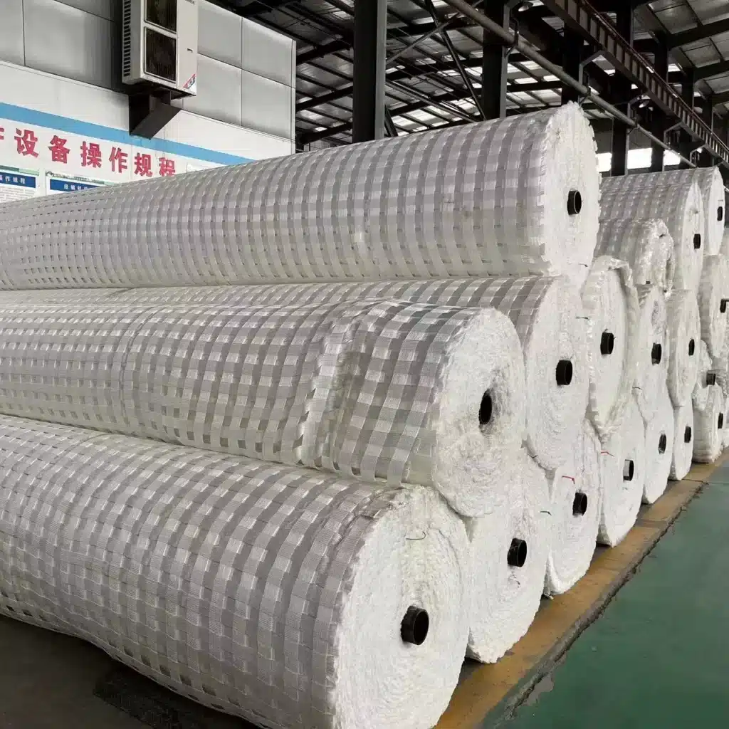
MJY manufactures uniaxial and biaxial geogrids with ISO-driven QA, engineered apertures for interlock, and certified long-term design strength. U get tuned specs, custom roll formats, and exporter-grade documentation for DOT-level submittals.
What U can expect from MJY
- Engineering support: Layer spacing, embedment, and drainage guidance matched to soils and loads.
- Product range: UX for steep/RSS, BX for veneer/base; UV-resistant, high-modulus polymers.
- Documentation: COA, lot traceability, and installation playbooks to reduce site errors.
- Supply assurance: OEM/private-label options, custom widths/lengths to cut waste and install time.