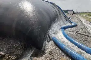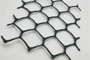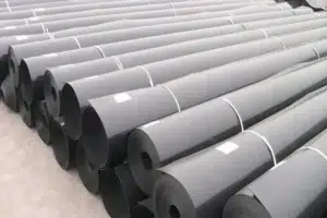
A retaining wall can look finished while its reinforcement is ineffective if the grid direction, length, backfill, connection, drainage, or compaction does not follow the approved detail.
Retaining wall geogrid should be installed only to the approved reinforcement layout: correct tensile direction, elevation, length, facing connection, backfill, drainage, lift thickness, and compaction sequence. A generic installation rule cannot replace the project wall design or the responsible engineer’s requirements.
The contractor checklist begins before the first roll is opened, because delivered material, wall geometry, working access, and the reinforcement schedule must agree with one another.
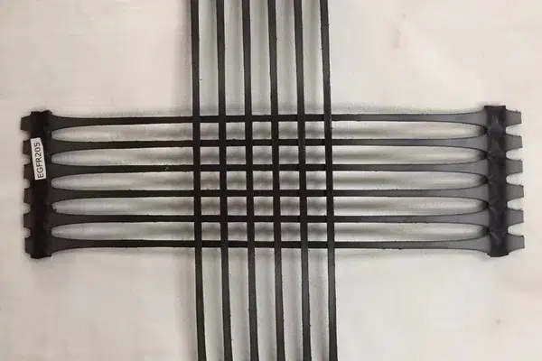
Send the wall section, reinforcement schedule, facing, backfill, drainage, roll dimensions, quantity, destination, and required documents for an RFQ review.
Request a retaining wall geogrid checkA retaining-wall geogrid RFQ should include wall height and geometry, facing type, reinforcement layers and lengths, specified tensile direction, backfill, drainage, surcharge conditions, roll size, quantity, destination, packaging, labels, and required test or approval documents. A roll strength alone is not a wall reinforcement schedule.
What Must Be Confirmed Before Installation?
Confirm the approved wall detail, grid type, tensile direction, layer elevations, reinforcement lengths, facing connection, backfill, drainage, and construction sequence before installation begins.
FHWA reinforced-soil wall guidance describes walls as systems that include reinforcement, compacted fill, facing, drainage, and construction controls. The material must match the approved system; a similar-looking grid should not be substituted without the required design review. [1]
Check roll labels against the schedule. The crew should know the intended orientation, coverage, layer number, and connection arrangement before the grid is cut or buried.
A good pre-start review also includes equipment access. If a roll is too wide, too narrow, or placed in the wrong direction, the crew may create unnecessary joints or cut reinforcement length that the design relies on.
Why Does Tensile Direction Matter?
The grid must be oriented so its intended reinforcement direction follows the approved load path. Turning a uniaxial grid sideways can make its specified strength irrelevant where the wall needs it.
The reinforcement schedule normally defines the direction away from the facing and the required length into the compacted soil mass. Field markings and roll labels should make this clear before each layer is placed.
ASTM D6637 is a tensile test method for geogrids. A reported test value supports product identification, but it does not authorize a different direction, length, connection, or wall layout from the approved design. [3]
Factory Tip: Before dispatch, compare the roll width and length with the wall layer schedule. This confirms usable coverage and reduces the risk of cutting material into short pieces that do not match the reinforcement layout.
| Project condition | What to confirm | Risk if missed |
|---|---|---|
| Wall reinforcement layer | Direction, length, elevation, connection | Strength not aligned with load path |
| Facing connection zone | Connection detail and access | Grid not engaged as designed |
| Backfill placement | Lift thickness, compaction, equipment route | Damage or displacement |
| Wet reinforcement zone | Drainage and moisture control | Poor compaction or water pressure |

How Should Geogrid Be Placed and Connected?
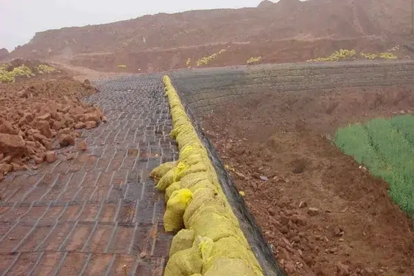
Place the grid flat at the specified elevation, connect it to the facing as detailed, extend it to the approved length, and keep it free of folds, damage, or unapproved splices.
The facing system and reinforcement connection are part of the wall system. Do not assume that overlap, tying, or field cutting creates an equivalent connection. Follow the approved detail and escalate a mismatch before the layer is covered.
Keep the grid tensioned only as required to remove slack and maintain line during fill placement. Excessive handling or equipment movement on exposed grid can shift the layer or damage the connection zone.
How Do Backfill, Drainage, and Compaction Affect the Wall?
Backfill quality, lift placement, compaction, moisture control, and drainage can change wall performance as much as the grid itself. Reinforcement does not make unsuitable saturated fill acceptable.
The project detail should identify the reinforced zone, accepted backfill, drainage layer, outlets, and compaction procedure. Water entering the reinforced mass can complicate compaction and may create conditions that the wall system was not designed to accept.
FHWA describes a GRS wall as a compacted soil mass reinforced by geosynthetic layers and used with a facing element. The full mass and construction process matter, not just the reinforcement roll. [2]
Field Note: One common site error is allowing equipment to turn or dump aggressively on a partially covered layer. The grid may remain hidden afterward, but the backfill density, layer alignment, or facing connection can already be compromised.
What Inspection Records Reduce Risk?
Record delivered roll labels, layer locations, elevations, lengths, connection checks, backfill source, compaction inspections, drainage work, and any approved site changes before the next lift covers the evidence.
Inspection records link delivered material to the reinforcement placed in the wall. They are especially useful when a roll is changed, a layer is adjusted, or a site condition requires engineering review.
QC Check: Stop work and refer to the approved detail when the grid appears too short, the direction is unclear, the backfill is unsuitable, water enters the reinforced zone, or the facing connection cannot be made as shown.
What Should Buyers Include in a Wall Geogrid RFQ?
Include the wall drawing, height, facing, reinforcement schedule, backfill, drainage, surcharge, grid direction, roll preference, quantity, destination, packing, schedule, and required documents.
The supplier can help compare roll dimensions and documents, but the project engineer should confirm final reinforcement design parameters. This distinction avoids turning a product quote into an unsupported structural approval.
Buyers can review geogrid for retaining walls, compare soil reinforcement applications, and send the section through the retaining wall geogrid RFQ form before order release.
FAQs
Can any geogrid be installed in a retaining wall?
No. The material, tensile direction, length, spacing, connection, backfill, drainage, and facing must match the approved reinforced-soil wall design.
Can geogrid be cut shorter to fit the site?
Not without the required design review. Reinforcement length is part of the wall system and should follow the approved schedule.
What should be inspected before covering each layer?
Check roll label, direction, length, elevation, facing connection, backfill, compaction, drainage, visible damage, and any approved field changes.
Conclusion
Retaining-wall geogrid installation is a design-controlled sequence. Confirm direction, length, connection, backfill, drainage, compaction, and records before each layer is buried.